
LaskaKit ESPwled
Kód: LA100066I LA100066P Zvolte variantu


Detailní popis produktu
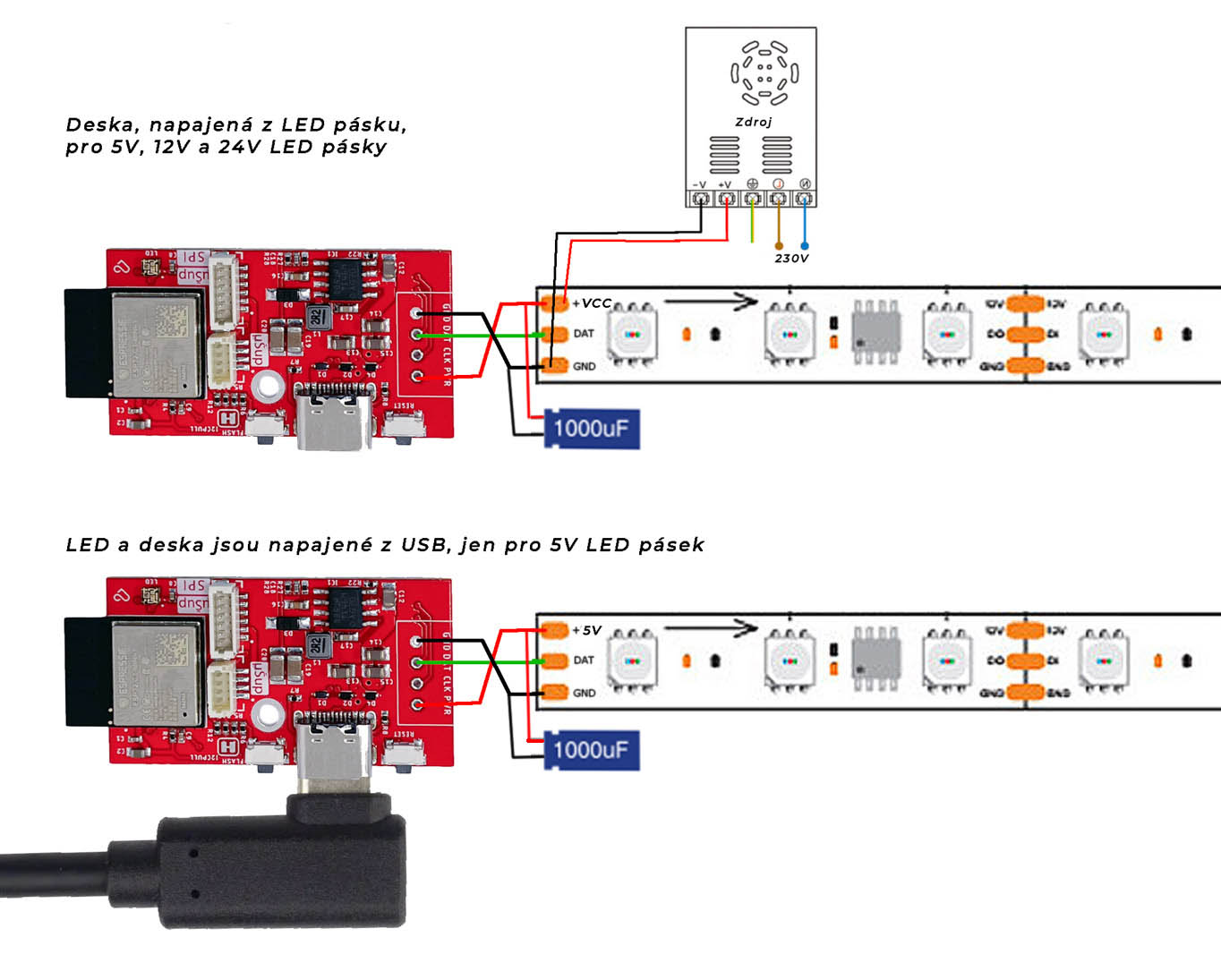
Hledáš desku, která je kompatibilní s projektem WLED, který přináší naprosto jednoduché ovládání nejrůznějších LED pásků bez nutnosti programování? Pak už dál hledat nemusíš. Program WLED do Laskakit ESPwled nahraješ jednoduše z webového prohlížeče projektu.
Nejprve připojíš desku skrze USB-C kabel a pak ESP32-C3, na kterém je deska založena, do nahrávacího režimu. To provedeš tak, že zmáčkneš a držíš tlačítko FLASH, zmáčkneš a uvolníš tlačítko RESET a poté uvolníš i tlačítko FLASH. Poté v prohlížeči vybereš připojenou Laskakit ESPwled desku a nahraješ program. Připojíš se na AP (Wi-Fi access point), kterou ESPwled vytvořil, přes třeba tvůj telefon a vyplníš jméno a heslo tvé Wi-Fi. Poté se ESPwled už připojí do tvé wifi a přes tvůj prohlížeč v telefonu, počítači nebo tabletu ovládáš připojené LED pásky.
DAtový GPIO pin, který se používá na ovládání LED pásků je 5, ne pin 2 jak je ve výchozím nastavení WLED -> je tedy v nastavení WLED tento pin změnit skrze webový prohlížeč. Pokud má LED pásek i CLK signál, ten je připojen na GPIO 4.
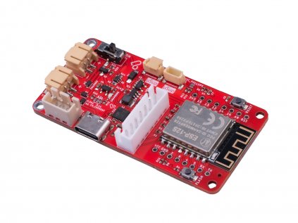
Deska samotná obsahuje navíc náš univerzální I2C uŠup konektor ke kterým můžeš připojit nejrůznější čidla - SHT40 (teplota, vlhkost), BME280 (tlak, teplota, vlhkost), SCD41 (CO2, teplota, vlhkost), BH1750 (osvětlení), APDS-9960 (senzor gest) a spoustu další senzorů.
Náš I2C uŠup konektor je kompatibilní s Adafruit Stemma a Qwiik od Sparkfun.
I2C sběrnice je připojeno takto, SDA GPIO10, SCL GPIO8. Je potřeba před iniciací i2c modulu přidat definici na kterých PINech jsou: Wire.begin(10, 8); // (SDA,SCL)
Kromě I2C uŠup konektoru má deska i SPI uŠup konektor, ke kterému můžeš připojit další SPI periférie.
ESPwled má osazenou adresovatelnou LED připojenou na GPIO 9. Pro ovládání této LED máme předpřiravený vlastní vzorový kód na našem github.
Dodatečné možna budeš potřebovat: Deska je dodávána bez LED konektoru, rozteč je 2.54mm. Můžeš dokoupit 1ks 4pin JST-XH pravoúhlýnebo 2ks 2 pin šroubovací svorkovnice do DPS KF128-2.54 anebo kolíkovou lištu. Vhodný pigtail s konektorem IPEX3 pro verze IPEX - Pigtail MHF3/IPEX3 - SMA Female, kabel 1,15mm, 15cm
Výchozí WLED firmware nepodporuje vstup z mikrofonu pro ESP32-C3 (ESPwled), pokud je mikrofonní vstup potřeba, je nutné si zkompilovat WLED firmware s jiným nastavením.
Dodatečné možna budeš potřebovat:
- Deska je dodávána bez LED konektoru, rozteč je 2.54mm. Můžeš dokoupit 1ks 4pin JST-XH pravoúhlý nebo 2ks 2 pin šroubovací svorkovnice do DPS KF128-2.54 anebo kolíkovou lištu.
- Vhodný pigtail s konektorem IPEX3 pro verze IPEX - Pigtail MHF3/IPEX3 - SMA Female, kabel 1,15mm, 15cm
- LaskaKit ESPwled adaptér pro LED pásek JST-SM-3
- LaskaKit ESPwled IP67 adaptér pro LED pásek
Specifikace:
| Verze v prodeji | V1.0 |
| ESP modul | ESP32-C3 |
| Flash | 4MB |
| Vstupní napětí |
USB-C: 5V (pouze pro 5V LED pásky) |
| Konektor pro anténu(IPEX verze) | IPEX3 |
| Pinout | GPIO |
| Integr. LED | 9 |
| LED DATA | 5 |
| LED CLOCK (jen pro 2 vodičové LED, např. APA102) | 4 |
| I2C SDA | 10 |
| I2C SCL | 8 |
| Rozměry | |
| Délka | 46mm |
| Šířka | 23mm |
| Výška | 8mm |
| Váha | 6g |
Součásti dodávky:
- 1ks LaskaKit ESPwled
Poznámka:
- Tento výrobek není samostatně funkčním celkem a může vyžadovat odbornou montáž.
- Fotografie výrobků jsou pouze ilustracemi na ukázku a někdy se mohou lišit od skutečného vzhledu předmětu. Avšak toto nemění jejích základní vlastnosti.
- 3D Tištěná krabička není součásti balení, můžete ji vytisknout nebo zakoupit zvlášť.

Výpis hodnocení
 Miroslav Vallo
 Michael Ondrášek
 Karel Funda
 Karel Král
Výpis diskuzí
 Vystupni napeti data pinu
Tono
Vystupni napeti data pinu
Tono
 Vystupni napeti data pinu
Martin Frajdl
Vystupni napeti data pinu
Martin Frajdl
 problem s WIFI
David Hruška
problem
David Hruška
problem s WIFI
Martin Frajdl
David Hruška
problem s WIFI
David Hruška
problem
David Hruška
problem s WIFI
Martin Frajdl
David Hruška
 Jakub
Jakub
 Vít Hrnčíř
 Čtyři pásky? :-D
Květoslav Janulík
Čtyři pásky? :-D
Vít Hrnčíř
Čtyři pásky? :-D
Květoslav Janulík
Čtyři pásky? :-D
Vít Hrnčíř
 Dva pásky?
Petr
Dva pásky?
Petr
 Dva pásky?
Konstantin Láska
Dva pásky?
Konstantin Láska
 Pískot/šum
Honza
Pískot/šum
Honza
 Driver
Jirka
Driver
Jirka
 kdy se povede naskladnit
Jiri
kdy se povede naskladnit
Konstantin Láska
kdy se povede naskladnit
Jiri
kdy se povede naskladnit
Konstantin Láska
 ws2814
Michal
ws2814
Martin Frajdl
ws2814
Michal
ws2814
Martin Frajdl
 Mikrofon a Audio Reactive
Tvoje Máma
Mikrofon a Audio Reactive
Tvoje Máma
 co se zapojuje na čtyř a pěti GPIO piny ?
Martin
co se zapojuje na čtyř a pěti GPIO piny ?
Konstantin Láska
Škoda za kondenzátor není na desce
Karel Král
co se zapojuje na čtyř a pěti GPIO piny ?
Martin
co se zapojuje na čtyř a pěti GPIO piny ?
Konstantin Láska
Škoda za kondenzátor není na desce
Karel Král